
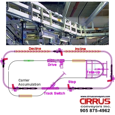
System Specifications
Free Trolley Load Centers
Using a typical free trolley set (leading and trailing trolley) with load bar, the minimum load bar accumulation centers are approximately 24-inches.
Pusher Dog Centers
Pusher dogs are solid cast steel with integral front pendant and loose rear pendant for attaching to the conveyor chain. Pusher dogs can be installed on a minimum of 12-inch centers.
Load Capacity
The maximum load that can be suspended from a 2-trolley load bar is 1,000 pounds.
Chain Pull
Chain pull is the force required to overcome the rolling resistance of the conveyor chain. The chain pull on a given system is proportional to the individual load weights, load centers, quantity of elevation changes, quantity of horizontal curves and overall environment that the system operates in. An average system chain pull will typically range between 1.5% and 5% of the sum of the moving load. Maximum chain pull for a single caterpillar drive is 750-pounds.
Contact Cirrus for chain pull calculations that relate to your system.
Typical System Components
Power Rail Components
See our FastTrack Conveyor System page for details on the power components of Cirrus FastTrack Power & Free.
Pusher Dogs
Pusher dogs provide the connection between the powered chain and the free rolling trolley / load bar assembly that carries product loads. Pusher dogs are constructed from solid cast steel with integral front pendant and loose rear pendant for attaching to the conveyor chain. The bolted assembly method allows for dog replacement without having to break the conveyor chain.
P&F Track
Straight track is comprised of roll formed 3/16" wall enclosed track positioned over a pair of 3-inch channel tracks, all tied together with flame cut track yokes.
The overall track dimension, measured from the top of the track yoke to the bottom of the 3-inch channels is 12 -1/2 inches. The overall width including track yoke measures 8 13/16 inches. Track is finish painted beige and is available in 10-foot lengths.
Each system will contain at least one chain installation gate which also serves as an inspection port. This straight section of track is open at the top and is protected by a cover that slides on. The overall length of an inspection section is 24-inches.
Each system will also contain at least one free trolley installation gate. This gate allows open access to the 3-inch channel track where free trolleys can be installed or removed from the system.
P&F Horizontal Track Curves
Horizontal curves are formed from straight enclosed track sections and roll formed 3-inch channel tracks, all tied together with flame cut track yokes. Common radii available include 24, and 36-inch centerline radius. The most common are 24-inch centerline radius. Curves are typically shipped in segments of 30-degree, 45, 90 and 180-degrees.
P&F Vertical Track Curves
Vertical track curves are formed from straight enclosed track sections and roll formed 3-inch channel tracks, all tied together with flame cut track yokes. In order to complete a change in elevation, two types of vertical curves are required. A lower vertical curve leads the chain from level to an incline and a top vertical curve takes the chain from an incline back to a horizontal position. Straight track situated between the vertical curves can be added to increase the overall incline or decline of the elevation change.
Track elevation changes use tight bite track to ensure that loads can never disengage from the claw dogs. Standard straight track has a drop of 7 -7/16 inches (measured from the bottom of the power track to the bottom of the free track). Tight bite track arranges the power track and free tracks closer together measuring 6-3/8 inches, resulting in no available space for the lead trolley flipper dog to pivot out of the pusher dog. Transition sections of track are used leading into and exiting elevation changes to match the tight bite track drop dimension.
Top curves are available with 30-inch chain centerline radius. Bottom vertical curves come with a 30-inch centerline free track radius. Curves are typically shipped in segments of 30-degree, and 45-degrees.
